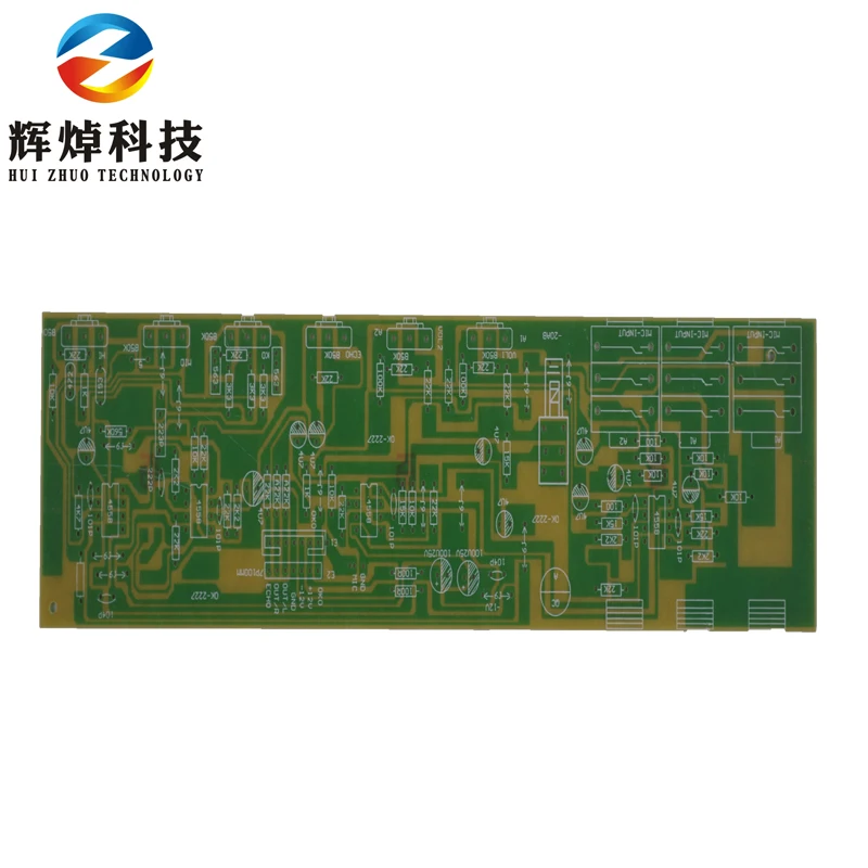
It’s recommended to place all surface mount device (SMD) components on the same side of the board. If you can eliminate net crossings with creative component placement, it will be easier to implement the best routing guidelines for a PCB layout. Each net intersection will require a layer transition through vias.

It's best to try and minimize the number of crossing nets.
Try to avoid crossing nets. When components are placed in the PCB layout, the unrouted nets are normally visible. Locating these components centrally makes trace routing easier in the PCB layout. Place large processors and ICs. Components like high pin count ICs or processors generally need to make connections to multiple components in the design. It's best to place these components first and lock-in their position before proceeding to the rest of the layout. There are often components that must be placed in specific locations, sometimes due to mechanical enclosure constraints or due to their size. These points can be difficult to balance, but a simple process can help a designer place components that meet these requirements: In addition, the design has to comply with the design rules and satisfy must-have component placements. The goal in component placement is to create a board that can easily routed, ideally with as few layer transitions as possible. The component placement stage of your PCB layout design process is both an art and a science, requiring a strategic consideration about the prime real estate available on your board. #2 - Fine-Tuning Your Component Placement Once these points are determined, you should select the more conservative design layout limits needed to ensure manufacturability and reliability, and you can encode these into your design rules. 
Once you've found their list of capabilities, you should compare these to whatever industry reliability standard you'll work with (Class 2 vs. It's best to do this first before you start placing components. While you're at it, make sure to submit your proposed stackup for review, or look for their standard stackup data and use that. If it's not in an obvious location on their website, send them an email and ask for their capabilities. A good fabricator will usually post their capabilities online or will supply this information in a document. The first place to start is to talk to your PCB fabrication house. There are some simple clearances that, if determined early in the design, will eliminate a lot of component shifting and re-routing later. When starting a new printed circuit board design, it’s sometimes easy to forget about the important design rules that will govern your project. #1 - Determine Your PCB Design Rules Before Layout Obeying mechanical constraints, such as connector locations and enclosure limitations.Location of power and ground in the PCB stackup, including some points for mixed signal PCB layouts.

Grouping components by type to prevent the need to route all over the board. Component placement, where the goal is to ensure solvability and ease of routing. Defining design rules with the goal of ensuring fabrication and assembly yield. The guidelines shown here are focused in a few key areas that will help you with routing, manufacturability, basic signal integrity, and assembly: Specialty designs may need to follow additional board layout guidelines, but the PCB layout guidelines shown here are a good place to start for most designs. In this guide, we've compiled some of the essential PCB layout guidelines that apply to most modern circuit boards. Whether you are moving at a high speed or you're designing a high speed printed circuit board, good design practices help ensure your design will work as intended and can be manufactured at volume. Determine Your PCB Design Rules Before Layout.


 0 kommentar(er)
